BRAKE SYSTEM
1988 Jeep Cherokee
1988 BRAKES
Jeep - Brake System
Cherokee, Comanche, Grand Wagoneer, Wagoneer, Wrangler
DESCRIPTION
DISC BRAKES
Floating caliper disc brake assembly uses a single piston caliper which "floats" on 2 bolts. As brake pedal is depressed, hydraulic pressure is passed through a proportioning valve to brake caliper piston.
This force is transmitted to inboard brake pad, forcing it against braking surface of rotor. Pressure then moves outer caliper housing and pad inward on caliper mounting bolts, thus forcing outer pad against outer braking surface of rotor.
DRUM BRAKES
Self-centering type system uses primary and secondary brake shoes with cable operated automatic adjusters. Brake shoe anchor is located at upper end of shoes above wheel cylinder. Single double acting brake cylinder is used.
MASTER CYLINDER - EXCEPT GRAND WAGONEER
The Delco Quick Take-Up master cylinder is used with systems utilizing low drag calipers. Master cylinder includes a quick take-up valve which delivers a large volume of fluid, at low pressure, upon initial brake application.
MASTER CYLINDER - GRAND WAGONEER
Bendix and Delco-Moraine tandem dual piston master cylinders are single casting type with front and rear pistons and a separate reservoir and outlet for each piston. Primary piston is operated by push rod connected to brake pedal. Secondary piston is operated by primary piston.
ADJUSTMENTS
NOTE: For Hub, Bearing and Axle Shaft Removal, Installation and
Adjustment information, see appropriate DRIVE AXLES article.
DISC BRAKE PADS
Automatic adjustment is provided by outward relocation of piston as lining wears.
DRUM BRAKE SHOES
1) Rear brake shoes adjust automatically as brakes are
applied while vehicle is operated in reverse. Drive vehicle in reverse applying brakes firmly 10-15 times, between each reverse brake application, drive vehicle forward and press brakes firmly.
2) Manual adjustment is required if shoes have been removed
and reinstalled. Brake shoes can be manually adjusted by rotating adjuster screw. Remove access slot cover.
3) Using a small blade screwdriver, push in on adjustment lever to separate from adjustment screw. Turn adjustment screw until brake drum is locked tight. Back screw off until wheel rotates freely. If brake drum is to be removed, back off adjustment screw several notches for adequate clearance.
HEIGHT SENSING PROPORTIONING VALVE - COMANCHE
NOTE: Anytime adjustment is required the lever bushing must be replaced.
Adjustment must be made on a drive-on lift or a flat level surface with vehicle at curb weight. Remove height sensing proportioning valve shaft nut and washer. Disconnect valve lever and remove spring. Remove and discard bushing.
Rotate valve shaft to permit installation and proper alignment of valve adjusting gauge (J-35853-2).
NOTE: The gauge (J-35853-2) must be properly seated on the "D"
shape of the shaft and the lower mounting bolt of the valve. See Fig. 2. Also, all linkage components, excluding the spring, must be connected to the axle housing before installation of bushing.
Place lever bushing in lever. Using bushing installation tool (J-35853-1) press bushing along with lever onto valve shaft. Remove lever and adjusting to (J-35853-2) then install the spring. Install lever, washer and retaining nut. Tighten retaining nut to 100 Inch-lbs. (11 N.m). Connect spring to lever arm.
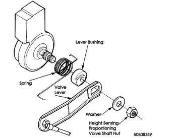
Fig. 1: Exploded View of Height Sensing Proportioning Valve
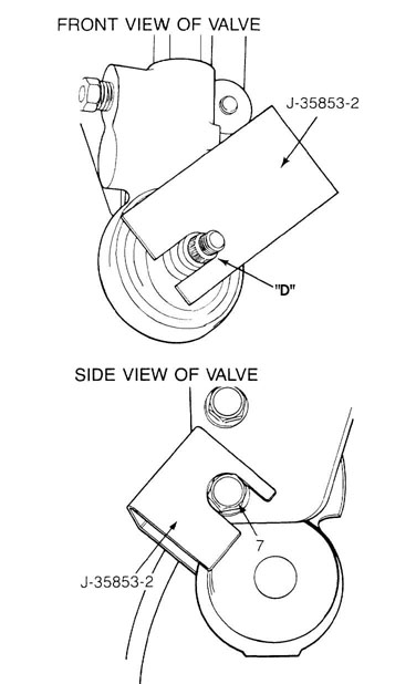
Fig. 2: Front and Side View of Valve Shaft
BACK VIEW OF VALVE
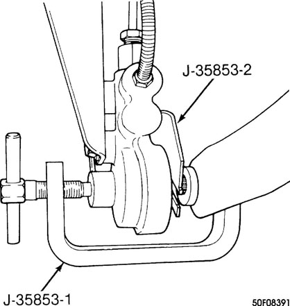
Fig. 3: Back View of Valve Shaft
PARKING BRAKE- EXCEPT GRAND WAGONEER
1) Adjust rear brakes. Check cable for binds, kinks or frayed condition. Replace cable (if necessary). Apply and release parking brake 5 times.
On all models except Wrangler, place parking brake lever
in fifth notch. Raise vehicle. Using Adjustment Gauge (J-34651), apply
a torque of 50-55 INCH lbs. (5-6 N.m). See Fig. 4.
Adjust nut on parking brake cable equalizer until pointer
is in Blue section of gauge. Apply and release parking brake cable 5
times. Check adjustment and readjust cable (if necessary).
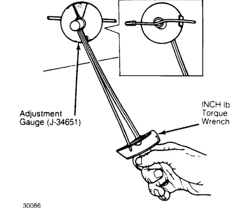
Fig. 4: Parking Brake Adjustment (Except Grand Wagoneer) Courtesy of American Motors/Jeep Corp.
PARKING BRAKE - GRAND WAGONEER
Adjust rear brakes. Check cable for binds, kinks or frayed
condition. Replace cable (if necessary). Release parking brake. Loosen
lock nuts at parking brake cable equalizer under vehicle.
Tighten cables until wheels drag slightly when rotated by
hand. Loosen equalizer until wheels rotate freely and no drag is felt.
Tighten lock nuts and check operation of parking brake.
ROTOR SERVICING
RUNOUT
Measure rotor lateral runout by mounting a dial indicator
on support stand or steering spindle. Position indicator stylus so it
contacts center of rotor braking surface.
Zero indicator and turn rotor one revolution. Note
indicator reading. Runout must not exceed specification. See DISC
BRAKE ROTOR SPECIFICATIONS table. Refinish or replace rotor (if
necessary).
NOTE: Thickness of machined rotor must not be below minimum thickness specification.
PARALLELISM
Measure rotor parallelism with a micrometer. Measure thickness at 4 or more equally spaced points around rotor at approximately 1" from edge of rotor. Variation must not exceed specification. See DISC BRAKE ROTOR SPECIFICATIONS table. Refinish or replace rotor (if necessary).
BRAKE SYSTEM BLEEDING
Hydraulic system bleeding is necessary any time air has been introduced into system. Bleed brakes at all 4 wheels if master cylinder lines have been disconnected or master cylinder has run dry. Bleed brakes with vacuum bleeding equipment, pressure bleeding equipment or by manually pumping brake pedal while using bleeder tubes. Always bleed brake lines in sequence. See BLEEDING SEQUENCE table.
MASTER CYLINDER BLEEDING
Bench Bleeding
Master cylinder must be bled before installation to
prevent excessive amounts of air from entering the brake system,
creating poor brake operation.
Place master cylinder in soft-jawed vise. DO NOT tighten
vise enough to damage master cylinder. Install bleeder tubes in both
outlets of master cylinder. See Fig. 5.
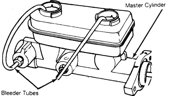
Fig. 5: Bleeding Master Cylinder Courtesy of American Motors/Jeep Corp.
Fill master cylinder with clean brake fluid that meets DOT
3 specifications. Ensure that the end of bleeder tubes are submerged
in the brake fluid.
Using proper sized rod, apply and release master cylinder
until no air bubbles exist in brake fluid flow. Once all air bubbles
are gone from master cylinder secure cap and install.
Bleeder tubes should be left installed on master cylinder
until master cylinder in installed. Master cylinder must be bled at
brake lines and wheels after installation.
Bleeding On Vehicle
Install master cylinder on vehicle after bench bleeding.
Remove bleeder lines and install brake lines. DO NOT fully tighten
brake lines at this time.
Slowly force brake pedal to the floor and hold in this
position. Tighten brake lines and release brake pedal. Repeat
procedure until no air bubbles exist at brake lines. Remaining wheel
cylinder or calipers may be require bleeding.
HYDRAULIC CONTROL VALVES
Hold Off Valve
Prior to the pressure tank bleeding procedure, the hold
off valve incorporated in the combination valve must be correctly
positioned. This allows brake fluid to flow through the combination
valve to the entire brake system.
The valve stem of the hold off valve may be retained using
tools available from Chrysler Motors (C-4121) or General Motors (J-23709) during bleeding procedure. See Figs. 6 and 7. Remove valve retainer once brake bleeding procedure is complete.
CAUTION: DO NOT use rigid clamp to position valve stem. Damage to the valve assembly may result causing brake failure.
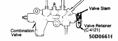
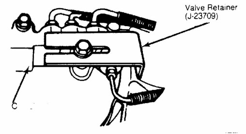
Fig. 7: Positioning Hold Off Valve Courtesy of American Motors/Jeep Corp.
VACUUM BLEEDING
Fill master cylinder. Install vacuum bleed equipment to first bleeder valve to be serviced. Open bleeder valve 3/4-1 turn. Depress vacuum pump and pull fluid into reservoir jar. Bleed each bleeder valve in sequence. See BLEEDING SEQUENCE table.
PRESSURE BLEEDING
Clean master cylinder cap and surrounding area. Remove
cap. With pressure tank at least 1/2 full, connect to master cylinder
with adapters. Attach bleeder hose to first bleeder valve to be
serviced. See BLEEDING SEQUENCE table.
Place other end of hose in clean glass jar partially
filled with clean brake fluid so end of hose is submerged in fluid.
The hold off valve must be positioned properly before pressure
bleeding (if equipped). See HYDRAULIC CONTROL VALVES under BRAKE
SYSTEM BLEEDING in this article.
Open release valve on pressure bleeder. Follow equipment
manufacturer’s pressure instructions or see PRESSURE BLEEDER SETTINGS
table. Open bleeder screw 3/4-1 turn and note fluid flow.
Close bleeder screw when fluid flowing is free of bubbles.
Repeat procedure on remaining wheels in proper sequence. Check brake
pedal operation after bleeding has been completed.
Remove pressure bleeding equipment and valve retainer from
hold off valve. Ensure that master cylinder is full of fluid.
MANUAL BLEEDING
NOTE: When bleeding disc brakes, air may tend to cling to caliper walls. Lightly tap caliper, while bleeding, to aid in removal of air.
Fill master cylinder. Install bleeder hose to first
bleeder valve to be serviced. See BLEEDING SEQUENCE table. Submerge
other end of hose in clean glass jar partially filled with clean brake
fluid. See Fig. 8.
Open bleeder valve 3/4-1 turn. Depress brake pedal slowly
through full travel. Close bleeder valve and release pedal. Repeat
procedure until flow of fluid shows no signs of air bubbles.
NOTE: When bleeding brake system manually, ensure bleeder valve is closed when brake pedal is released.
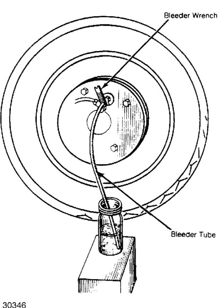
Fig. 8: Wheel Cylinder Bleeding Procedure Courtesy of American Motors/Jeep Corp.
BLEEDING SEQUENCE
Before bleeding system, exhaust all vacuum from power unit by depressing brake pedal several times. Bleed master cylinder (if equipped) with bleeder screws. Bleed slave cylinder on vehicles equipped with remote mount power assist units. Bleed wheel cylinders and calipers in sequence. See BLEEDING SEQUENCE table.
BLEEDING SEQUENCE TABLE
Application Sequence
All Models RR, LR, RF, LF
REMOVAL & INSTALLATION
DISC BRAKE CALIPER
Removal & Installation
Caliper removal and installation procedures are same as for disc pad replacement. To remove caliper from vehicle, disconnect brake line at caliper and cap hole to prevent contamination.
DISC BRAKE PADS
Removal
Drain 2/3 of brake fluid from master cylinder reservoir.
Raise vehicle and support with safety stands. Remove front wheel
assembly.
Place "C" clamp on caliper. Solid end of clamp should
contact back of caliper. Screw end should contact metal part of
outboard shoes.
Tighten "C" clamp until caliper forces piston to bottom of
bore. Remove both Allen head mounting bolts and lift caliper off
rotor. Support caliper out of the way.
On Grand Wagoneer, remove both brake pads from caliper.
Note spring position and support spring from inboard shoe. Remove
sleeves and bushings from caliper.
On all other models, hold anti-rattle clip against caliper
adapter and remove outer brake pad. Remove inner brake pad and anti-
rattle clip from caliper adapter.
Installation
To install, reverse removal procedure. On Grand Wagoneer,
lubricate new bushings, sleeves, bushing grooves, and small ends of
mounting bolts with silicone lubricant. Install rubber bushings in
caliper mounting ears.
On all other models, clean caliper mating surfaces on
adapter with a wire brush. Apply double sided adhesive tape to back
side of inner pad. Clean caliper piston surface. Lubricate caliper
mating surfaces on caliper adapter.
On all models, lubricate caliper mounting bolts using
brake corrosion lubricant and tighten mounting bolts. Add brake fluid
to reservoir. Apply brakes until brake pedal is firm. Check brake
fluid level.
DISC BRAKE ROTOR - WRANGLER
Removal
Raise and support vehicle. Remove front wheel and caliper. Suspend caliper from frame or suspension. Remove rotor from hub.
Installation
Clean hub and rotor mating surfaces. To install, reverse removal procedure.
NOTE: DO NOT disconnect brake hose from caliper unless caliper is
to be disassembled.
DISC BRAKE ROTOR - CHEROKEE, COMANCHE & WAGONEER
Removal
Raise and support vehicle. Remove front wheel and caliper.
Suspend caliper from frame or suspension. Remove cap, cotter pin, nut
retainer, adjusting nut and thrust washer from spindle.
Remove outer bearing from hub. Remove hub and rotor from
spindle. Remove hub and rotor seal. Remove inner bearing from hub.
Installation
Apply small amount of "EP" type waterproof wheel bearing
grease in hub cavity. Lubricate inner and outer bearings. Install
inner bearing and seal in rotor. Clean rotor surface (if necessary).
Install hub and rotor on spindle. Install outer bearing,
thrust washer and spindle nut. Tighten spindle nut to 17-25 ft. lbs.
(23-34 N.m) while rotating rotor to seat bearings. Loosen spindle nut 1/2 a turn and retighten an additional 19 INCH lbs (2 N.m). Reverse removal procedure to complete installation.
DISC BRAKE ROTOR - GRAND WAGONEER
Removal
Raise vehicle and support with safety stands. Remove wheel
and caliper. On models without front hubs, remove rotor hub cap, drive
gear snap ring, drive gear, pressure spring and spring cup.
On models with front hubs, remove screws attaching hub
body to hub clutch and remove hub body from clutch. Remove large and
small retaining rings. Remove hub clutch from axle shaft.
On all models, remove wheel bearing outer and inner lock
nuts and retaining ring using Socket (J-6893-D). Remove rotor. Remove
wheel bearings from rotor.
Installation
Lubricate bearings with "EP" type waterproof wheel bearing
grease. Install bearings and seal in rotor. Install rotor and inner
lock nut. Inner lock nut has a locating peg on one side. When
installed, peg must face away from bearing.
Install wheel, but do not tighten lug nuts completely.
Tighten inner lock nut to 50 ft. lbs. (68 N.m) while rotating wheel.
Back of inner lock nut 1/6 turn (45-65 degrees).
Install retaining washer. Ensure that inner lock nut
locating peg is engaged with retaining washer. Install outer lock nut
and tighten to 50 ft. lbs. (68 N.m).
On models without front hubs, install pressure spring cup,
pressure spring, drive gear and snap ring. Coat rim of chrome hub
cover with Permatex No. 3 and install cap in rotor hub.
NOTE: Recessed side of spring cup faces outer bearing and flat side faces pressure spring.
5) On models with front hubs, install hub clutch on axle.
Install large and small hub retaining rings. Install hub body on
clutch and tighten to 30 INCH lbs. (3 N.m). Reverse removal procedure
to complete installation.
DRUM BRAKE SHOES- EXCEPT GRAND WAGONEER
Removal
Raise vehicle and support with safety stands. Remove wheel
assembly and drum. Remove "U" clip and washer from parking brake lever
pivot pin. Place Wheel Cylinder Clamp (J-8002) over wheel cylinder.
Remove primary and secondary return springs, spring
retainers, hold-down springs and retaining pins. Remove adjuster
lever, adjuster screw and spring from brake shoes. Remove brake shoes.
See Fig. 9.
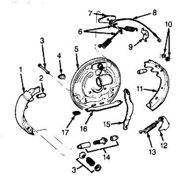
Fig. 9: Exploded View of Drum Brake (W/Cable Operated Adjuster) Courtesy of American Motors/Jeep Corp.
1) Secondary Brake Shoe
2) Wheel Cylinder Pin
3) Hold Down Pin
4) Acess Cover
5) Backing Plate
6) Return Springs
7) Guide Plate
8) Adjusting Cable
9) Cable Guide
10) Washer
11) Primary Brake Shoe
12) Adjustment Lever
13) Lower Return Spring
14) Self-Adjuster
15) Parking Brake Lever
16) Parking Brake Strut
17) Parking Brake Spring
Installation
1) Lubricate support plate ledges, anchor pin, adjuster cable guide, adjuster screw assembly, parking brake lever and lever pivot pin with molybdenum disulphide grease.
Connect parking brake lever to secondary brake shoe with
washer and "U" clip. Crimp ends of clip to secure clip on pivot.
Remove wheel cylinder clamp. Position brake shoes on brake support
plate and install hold-down springs.
Install parking brake lever strut and spring. Install
adjuster cable guide plate and adjuster cable on anchor pin. Install
primary return spring. Install guide to secondary brake shoe. Install
secondary return spring.
Install adjuster screw, spring and lever. Connect lever to
cable. Using Brake Gauge (J-21177-01), preset brake shoe adjustment.
Install brake drums. Adjust brake shoes with drum in place.
Install wheels and lower vehicle. To adjust and balance
brake system, apply and release brakes 10-15 times while driving
forward and backward. Road test vehicle.
DRUM BRAKE SHOES - GRAND WAGONEER
Removal
Raise vehicle and support with safety stands. Remove
wheels. On models with full-floating rear axle, remove 2 screws that
retain drum on hub.
On all models, remove primary shoe return spring,
automatic adjuster actuator spring and secondary shoe return spring. Remove hold-down springs. Remove brake shoe assemblies. See Fig. 10.
Disengage parking brake cable from parking brake lever.
Remove parking brake strut and brake shoe assembly as a unit. Place
wheel cylinder clamps over cylinders in order to retain pistons.
Inspect automatic adjuster lever and pivot, actuating
lever, parking brake lever, automatic adjuster and springs. Replace
weak springs, bent levers and parts that are worn or broken.
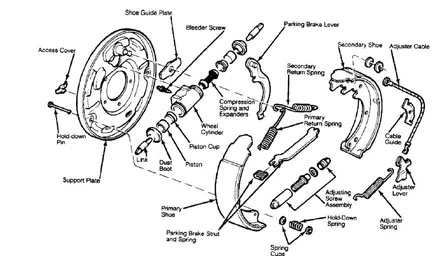
Fig. 10: Exploded View of Drum Brake Assembly (Grand Wagoneer) Courtesy of American Motors/Jeep Corp.
Installation
1) Clean support plate. Apply a thin film of molybdenum
disulphide grease or chassis lubricant on support plate ledges, anchor pin, adjuster screw threads and pivot.
Apply grease to adjuster lever-to-secondary brake shoe
contact surface, parking brake lever pivot and portion of lever that
contacts secondary brake shoe.
Attach parking brake cable to parking brake lever on
secondary shoe. Pinch "U" clip to retain lever on shoe. Install
secondary brake shoe, automatic adjuster lever and lever pivot as an
assembly.
Install brake shoe hold-down spring. Install return spring
on actuating lever tang. Large end of tapered spring should rest on
brake shoe.
Install primary shoe and hold-down spring. Install guide
plate on anchor pin. Install parking brake strut and spring on brake
shoes.
Install adjusting screw and spring. Short end of hooked
spring attaches to primary brake shoe. Long hooked end attaches to
secondary brake shoe.
Install secondary shoe return spring, adjuster spring and
primary return spring. Install brake drums. Adjust brakes. Bleed brake
system.
Install wheels and lower vehicle. Apply and release brakes
10-15 times while driving forward and backward to adjust and balance
brake system. Road test vehicle.
MASTER CYLINDER- EXCEPT GRAND WAGONEER
Removal
With engine off, depress brake pedal several times to
release vacuum in power unit. Clean dirt and grease from brake line
connections.
Disconnect and plug brake lines at master cylinder. Remove
retaining nuts and master cylinder.
Installation
To install, reverse removal procedure. Bleed brake system. See BRAKE SYSTEM BLEEDING in this article.
MASTER CYLINDER- GRAND WAGONEER
Removal
Disconnect brake lines at master cylinder and plug. On vehicles without power assist units, disconnect brake pedal push rod at brake pedal. Remove master cylinder retaining nuts at firewall. Remove master cylinder.
Installation
Master cylinder should be bench bled before installation.
See BRAKE SYSTEM BLEEDING in this article. Position master cylinder on
vehicle. Loosely install retaining nuts. Loosely install brake lines
to cylinder. Tighten retaining nuts. Tighten brake lines.
Connect brake pedal push rod (if removed). Fill reservoir
with brake fluid and bleed brake system. See BRAKE SYSTEM BLEEDING in
this article.
REAR AXLE BEARING & SEAL
Removal
1) Raise vehicle and support with safety stands. Remove wheel
assembly and brake drum. Remove support plate retaining nuts through
hole provided in axle flange. Use a slide hammer to remove axle shaft.
2) If wheel bearing cup remains in housing, use Slide Hammer
(J-2619-01) and Bearing Remover (J-26941) to remove bearing cups.
Remove axle shaft oil seal from axle housing tube.
3) Place axle shaft in a vise. Drill a 1/4" (6.35 mm) hole 3/4 of the way through bearing retaining ring. Chisel off bearing retaining ring. Do not use a torch. Press bearing off axle. Remove seal and retainer plate.
Installation
Lubricate bearing and seal lip. Install retainer plate and seal over axle. Press axle shaft bearing and retaining ring on shaft simultaneously. Ensure bearing and ring are seated against axle shaft shoulder. To complete installation, reverse removal procedure to complete installation.
WHEEL CYLINDER
Removal
Remove wheel assemblies, brake drums and brake shoes.
Disconnect brake line at wheel cylinder. Do not bend brake line away from cylinder. Remove cylinder-to-support plate bolts. Remove cylinder.
Installation
To install, reverse removal procedure. Start brake line fitting into cylinder before installing cylinder to support plate.
OVERHAUL
DISC BRAKE CALIPER
Disassembly
Clean caliper exterior with brake cleaning solvent. Drain
residual fluid from caliper and place caliper on a clean working
surface.
Remove piston from caliper by applying compressed air to
inlet port. Use just enough pressure to ease piston out of bore.
Protect piston from damage with folded shop towels. Do not try to
catch piston by hand.
Pry dust boot out of bore with screwdriver. Do not scratch
bore. Using a small plastic or wooden stick, pry piston seal from
bore. See Fig. 11. Remove bleeder screw, sleeves, and bushings.
Cleaning & Inspection
Clean all parts with brake cleaning solvent. Blow dry parts. Check for damaged or worn parts. Stains on piston bore can be polished with crocus cloth. Do not use emery cloth or any other abrasive.
Reassembly
Lubricate bore and new seal with brake fluid. Install seal
in groove using fingers. Lubricate piston with brake fluid. Slide
metal retainer portion of dust boot over open end of piston. Pull boot
rearward until boot lip seats in piston groove.
Push retainer portion of dust boot forward until boot is
flush with rim at open end of piston and boot fold snaps into place.
Insert piston in bore being careful not to unseat piston seal.
Push piston to bottom of bore using hammer handle.
Position dust boot retainer in counterbore at top of piston bore. Seat dust boot retainer with Dust Boot Installer (J-22904 or J-33028). Reverse removal procedure to complete installation.
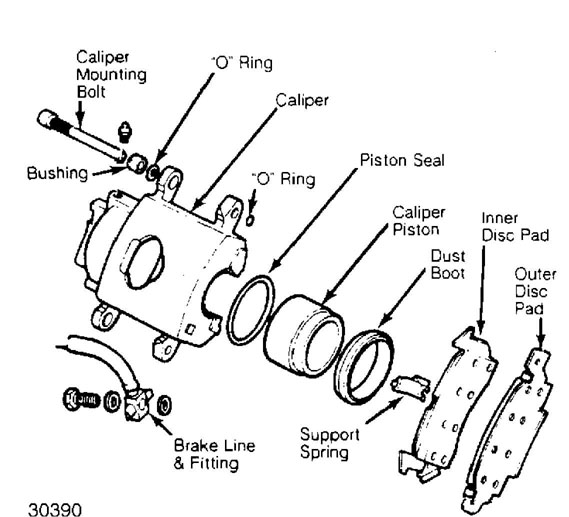
Fig. 11: Caliper Assembly (Grand Wagoneer) Courtesy of American Motors/Jeep Corp.
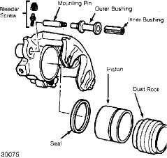
Fig. 12: Caliper Assembly (Except Grand Wagoneer) Courtesy of American Motors/Jeep Corp.
MASTER CYLINDER - EXCEPT GRAND WAGONEER
NOTE: Do not hone master cylinder. Bore has a highly polished
"Bearingized" surface. Honing will cause premature failure of rubber parts.
Disassembly
Remove reservoir cover and diaphragm. Drain remaining
brake fluid. Push in on primary piston and remove snap ring.
Carefully apply compressed air at forward brake line hole
while plugging rear hole. Use caution as piston will be forced out
open end of master cylinder with considerable force.
Remove spring retainer and seals from secondary piston.
Discard seals. Clamp mounting ear of master cylinder in vise and
carefully pry off reservoir.
Do not attempt to remove take-up valve from master
cylinder as it is not a serviceable component. Remove reservoir
grommets and discard.
Inspection
Inspect cylinder bore for scoring or corrosion. If signs of corrosion are evident, replace master cylinder. Use no abrasives on cylinder bore. Inspect reservoir cover and diaphragm for cuts, cracks or deformation. Replace damaged or defective parts as necessary.
Reassembly
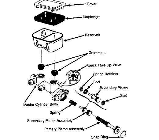
Fig. 13: Exploded View of Quick Take-Up Master Cylinder Courtesy of General Motors Corp.
Lubricate new reservoir grommets with clean brake fluid
and press into master cylinder. Ensure grommets are properly seated.
Lay reservoir on flat, hard surface. Rock master cylinder body onto
reservoir until completely seated.
Lubricate new piston seals with clean brake fluid and
install on secondary piston, with lip of seals toward ends of piston.
Install spring retainer.
Install secondary piston spring and secondary piston
assembly in master cylinder. Lubricate primary piston seals with clean
brake fluid.
Install primary piston in master cylinder. Press in piston
and install snap ring. Fit diaphragm in reservoir cover and install
cover.
MASTER CYLINDER- GRAND WAGONEER
NOTE: Do not hone master cylinder bore. Bore has a highly polished "bearingized" surface. Honing will cause premature failure of rubber parts.
Disassembly
Clean outside of cylinder thoroughly and remove cover.
Drain fluid. Pump piston to remove any remaining fluid. On
Delco/Moraine models with composite fluid reservoir, install metal
flange in vise and pry reservoir off with a pry bar. Bendix composite
reservoir is held on by 4 bolts on bottom of reservoir. On manual
brake models, remove boot from cylinder to uncover push rod retainer.
Pry up retainer tab to release retainer. Remove snap ring
from groove in cylinder bore. Remove both piston assemblies. Remove
remaining internal parts from bore. Note direction of piston seals.
Remove and discard all rubber parts from piston assemblies.
Tube seats can be removed if damaged. Enlarge holes in
tube seats using a 13/64" drill. Place a large flat washer over outlet
and thread a 1/4" x 20 x 3/4" screw into seat. Tighten screw until
seat is loose. See Fig. 14. Remove seat, screw and washer.
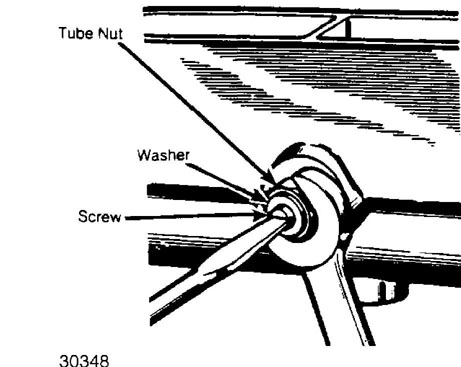
Fig. 14: Removing Tube Seat from Master Cylinder Courtesy of American Motors/Jeep Corp.
Inspection
Inspect cylinder bore for scoring or corrosion. Staining
which has not pitted or roughened surface of cylinder can be removed with crocus cloth. If cylinder bore is scored, pitted or corroded, replace master cylinder.
Reassembly
Install replacement tube seats by threading a spare brake
line tube nut into hole. Turn nut in until tube seat bottoms. Do not
cock tube seat in hole. Remove nut and check for burrs which may have
been loosened by nut. Install secondary seals on secondary piston,
with cup lips facing away from each other.
Install primary seal, spring retainer and return spring on
secondary piston. Install seal so lip faces interior of master
cylinder when installed. Lubricate cylinder bore with clean brake
fluid and install secondary piston assembly. Lubricate primary piston
seals and install primary piston assembly in bore. Hold primary piston
downward in bore and install snap ring.
Install composite reservoir (if equipped). On models with
push-on composite fluid reservoir, invert reservoir, install grommets
and press on body using a rocking motion. Install master cylinder
cover and new diaphragm.
On vehicles with manual brakes, assemble brake pedal push
rod through retainer (if equipped). Push retainer over end of master
cylinder and install rubber boot.
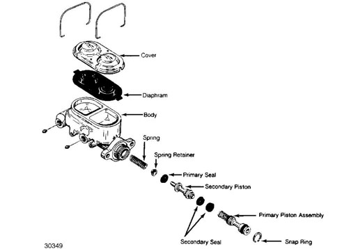
Fig. 15: Exploded View of Master Cylinder (Grand Wagoneer) Courtesy of American Motors/Jeep Corp.
WHEEL CYLINDER
Disassembly
Remove dust boots. Push pistons, piston cups and expander spring out of bore. Discard cups. Clean all parts with brake solvent. Inspect cylinder bore and piston for pitting, wear or damage. Replace as necessary. Light scoring or pitting may be removed by honing.
Reassembly
Lubricate cylinder bore and internal components with brake
fluid. Do not lubricate dust boots. Position replacement piston cups
on spring expanders. Install assembled parts in cylinder bore.
Ensure expanders are seated in piston cups. Cups are to be
installed with lips facing each other. Install pistons with flat sides
facing interior of bore. Install dust boots.
TORQUE SPECIFICATIONS
TORQUE SPECIFICATIONS TABLE
Application Ft. Lbs. (N.m)
Disc Brakes
Caliper Mounting Bolts 35 (47)
Bleeder Screw 12 (16)
Brake Line-to-Caliper 13 (18)
Drum Brakes
Wheel Cylinder Bolts 11 (15)
Bleeder Screw 1/4" 4-5 (5-7)
Bleeder Screw 3/8" 4-10 (5-14)
Brake Line 10-17 (14-23)
Backing Plate Bolt 30-40 (41-54)
Master Cylinder Retaining Nuts
Except Grand Wagoneer 20 (27)
BRAKE SYSTEM SPECIFICATIONS
DISC BRAKE SPECIFICATIONS
DISC BRAKE SPECIFICATIONS TABLE
Application In. (mm)
Cherokee, Comanche, Wagoneer & Wrangler
Disc Diameter 11.02 (279.9)
Lateral Runout 0.005 (0.13)
Parallelism 0.001 (0.03)
Original Thickness 0.88 (22.4)
Min. Refinish Thickness 0.815 (20.70)
Discard Thickness 0.815 (20.70)
Grand Wagoneer
Disc Diameter 12.00 (304.8)
Lateral Runout 0.005 (0.13)
Parallelism 0.001 (0.03)
Original Thickness N/A
Min. Refinish Thickness 1.215 (30.86)
Discard Thickness 1.215 (30.86)
DRUM BRAKE SYSTEM SPECIFICATIONS
DRUM BRAKE SPECIFICATIONS TABLE
Application In. (mm)
Cherokee, Comanche, Wagoneer & Wrangler
Drum Diameter 10.00 (254.0)
Drum Width 1.75 (44.5)
Max. Drum Refinish Diam 10.06 (255.5)
Wheel Cyl. Diameter 875 (22.2)
Master Cyl. Diameter 937 (23.8)
Grand Wagoneer
Drum Diameter 11.00 (279.4)
Drum Width 2.00 (50.8)
Max. Drum Refinish Diam 11.06 (280.9)
Wheel Cyl. Diameter 937 (23.80)
Master Cyl. Diameter 1.125 (28.58)
