INTRODUCTION JEEP AW-4
The AW-4 is a four speed, electronically controlled automatic transmission. Running gear consists of a lock-up converter: oil pump:three planetary gear sets: clutch and brake units:hydraulic accumulators:a valve body with electric solenoids and a transmission computer unit "TCI". Cables are used for shifting and throttle pressure control. A neutral safety switch permits engine starting in Park and Neutral range only. The valve body solenoids are controlled by signals from the TCU. Signal sequence is determined by vehicle speed and throttle position. Fourth gear is an .70:1 ratio overdrive range. First second.third and reverse gear are conventional ranges. Third gear ratio is 1:1. A separate planetary gear set provides overdrive operation in fourth gear.
We thank the Chrysler Corporation for the
illustrations and information that have
made this booklet possible
ROBERT D.CHERRNAY TECHNICAL DIRECTOR
WAYNE COLONISA TECHNICAL SUPERVISOR
PETER LUBAN TECHNICAL CONSULTANT
GREGORY LIPNICK TECHNICAL CONSULTANT
DAVID CHALKER TECHNICAL CONSULTANT
DALE ENGLAND FIELD SERVICE CONSULTANT
ED KRUSE
TECHNICAL CONSULTANT
JIM DIAL
TECHNICAL CONSULTANT
JERRY GOTT
TECHNICAL CONSULTANT
ARSENIO RIVERA TECHNICAL CONSULTANT
AUTOMATIC TRANSMISSION SERVICE GROUP
9200 S. DADELAND BLVD. SUITE 720
MIAMI, FLORIDA 33156
(305)670-4161
JEEP AW-4
INDEX
Transmission System 3
Diagnosis 7
Troubleshooting 10
Transmission Service 13
Transmission & Torque Converter Removal 26
Transmission Overhaul 28
Sub-Assembly Overhaul *1
Valve Body Teardown 79
Transmission Assembly 95
AUTOMATIC TRANSMISSION SERVICE GROUP 9200 S. Dadeland Blvd.
Suite 720
MIAMI FLORIDA 33156 (305) 670-4161
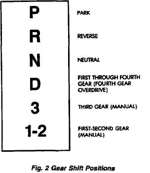
GEAR SHIFT POSITIONS
The AW-4 transmission has six gear shift lever positions. Park, Reverse and Neutral positions are conventional and mechanically operated. The 1-2,3 and D ranges provide electronically controlled shifting.
The 1-2 position provides first and second gear only. The 3 position provides first, second and third gear. The D range provides first through fourth gear. Overdrive fourth gear range is available only when the shift lever is in D position (Fig. 2).
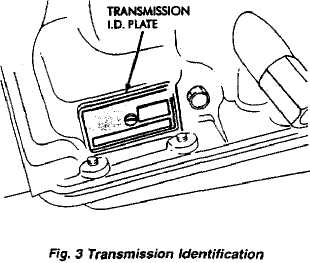
TRANSMISSION IDENTIFICATION
The transmission I.D. plate is attached to the case (Fig. 3). The plate contains the transmission serial and model numbers. Refer to the information on this plate when ordering service parts.
COMPONENTS AND OPERATION
Electronic Controls
The AW-4 is electronically controlled in the forward gear ranges. The controls consist of the TCU. valve body solenoids and sensors that monitor vehicle speed, throttle opening, shift lever position and brake pedal application.
TCU
The TCU determines shift and converter lockup timing based on signals from the sensors. The valve body solenoids are activated/deactivated accordingly.
The TCU has a self diagnostic program. Component and circuitry malfunctions can be diagnosed with the
DRB ¨k tester. Once a malfunction is noted and stored in TCU memory, it is retained even after the problem has been corrected. To cancel a stored malfunction, simply disconnect and reconnect the Trans." fuse in the TCU harness.
Shift Modes
Two separate shift modes are programmed into the TCU. The Comfort mode provides normal shift speeds and points. The Power mode provides higher engine speeds and shift points when extra acceleration and torque are needed. The shift modes are activated by a switch in the instrument panel.
Valve Body Solenoids
The solenoids are mounted on the valve body and operated by the TCU. The solenoids control operation of the converter lockup and shift valves in response to input signals from the TCU.
Sensors
The sensors include the throttle position sensor (TPS), the speed sensor, the neutral safety switch and the brake pedal application switch.
The throttle position sensor is mounted on the throttle body. It electronically determines throttle position and relays this information to the TCU to control shift points and converter lockup.
The speed sensor consists of a rotor and magnet on the transmission output shaft and a switch in the extension housing or adapter. The sensor switch is activated each time the rotor and magnet complete one revolution. Sensor signals are transmitted to the TCU.
The neutral safety switch is mounted on the valve body manual shaft. The switch signals shift linkage and manual valve position to the TCU through an interconnecting harness. The switch prevents engine starting in all gears other than Park or Neutral.
The brake application switch releases the lock-up clutch in the torque converter whenever the brakes are applied. The switch is mounted on the brake pedal bracket and signals the TCU when the pedal is pressed or released.
TORQUE CONVERTER
A lockup torque converter is used for all applications. The lockup mechanism consists of a sliding clutch piston, clutch springs and the clutch disc material (Fig. 4).
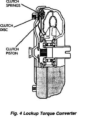
The disc is attached to the converter front cover. The clutch piston and clutch springs are attached to the
turbine hub. The springs dampen engine firing im pulses and loads during the initial phase of converter lockup.
Lockup is controlled by valve body solenoid number three and by the lockup relay valve. At lockup speed, the solenoid channels line pressure to the lockup clutch through the relay valve.
Torque converter lockup occurs in second gear in 1-2 position; third gear in 3 position and third and fourth gear in D position.
FOURTH GEAR OVERDRIVE COMPONENTS
The overdrive system consists of the input shaft, oneway clutch, planetary sun gear, ring gear, planetary carrier, direct clutch and overdrive brake (Fig. 5). The overdrive elements are controlled and applied through valve body solenoid number two.
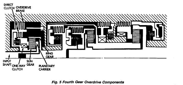
In overdrive fourth gear, the brake prevents the overdrive sun gear from turning. During operation, the overdrive elements operate as follows:
The overdrive input shaft and planetary carrier ro tate as a unit. The sun gear and overdrive direct clutch drum are in mesh and operate as a single unit. The direct clutch splines function as the hub for the overdrive brake. The one-way clutch outer race is in mesh with the planetary carrier. The inner race is fixed to the sun gear shaft.
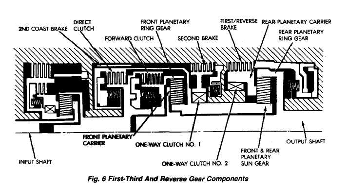
FIRST-THIRD-REVERSE GEAR COMPONENTS
First-third and reverse gear components are outlined in Figure 6.
The input shaft is meshed with the direct clutch hub and the forward clutch drum. These elements rotate as a unit. The forward clutch hub rotates as a unit with the front planetary ring gear. The direct clutch drum is meshed with the forward end of the planetary sun gear.
The second brake hub serves as the outer race of one-way clutch No. 1. The clutch inner race is locked with the front/rear sun gear. The inner race of one-way clutch No. 2 is splined to the transmission case and is locked. The outer race rotates as a unit with the rear planetary carrier.
The rear planetary ring gear is splined to the output shaft. The front planetary carrier and rear carrier ring gear are meshed and rotate as a unit with the output shaft.
GEARTRAIN OPERATION AND APPLICATION CHARTS
Operation and application of the first through fourth and reverse gear elements are outlined in the function and application charts.
The Component Function Chart (Fig. 7) describes basic function of various geartrain elements, The Component Application Chart (Fig. 8) indicates which elements (including valve body solenoids!, are applied in the various gear ranges.